Experimental program to transfer digital images and texts by JJ0OBZ
Many thanks to Roland PY4ZBZ for allowing me to translate this infomation into English and publish on my site. Paul G0HWC
By PY4ZBZ on 6/10/2010 rev. 30-06-2010 06/30/2010
On 29.06.2010 was released the second version of STV Ver.1.0.1 buid KG-000.
For latest version and download links click HERE
The main novelties compared to previous version, described in more detail below, are:
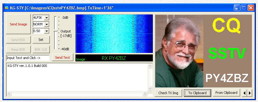
1 – Spectrogram or “waterfall” of the received signal in the same window of the eye diagram and can switch from one to another with a click in the window. The waterfall also lets you adjust the tuning frequency of the SSB receiver, with the help of two vertical strokes, as shown above.
2 – The option “AutoSave” is now on the “Set” of settings (Settings). If checked, the images received will be saved in the “AutoSave” with names formed by “data_hora_prefixotx.jpg” and that can be seen with the “arrows to the right / left. There are also buttons “To and From Clipboard” that allow to save or retrieve an image from the Windows clipboard.
3 – Now KG-STV informing the prefix of who is transmitting, and must be set to “Set” at the plant. This prefix appears in the transmission and receipt, below the window or the waterfall, appears as shown below.
4 – The “Check TX Img” lets you see the image that is loaded into the transmit buffer, even having received another image on screen, or recalculate the transmission time indicated in the title bar, after switching modes or TX compression ratio.
This is a program that actually deserves the name of SSTV, it works by mimicking the old style and dedicated analog SSTV, slow-scan television. But unlike the analog SSTV, which scans the image line by line, KG scans the image in blocks of 16×16 pixels, ie 15 scan lines each consist of 20 blocks of 16×16 pixels, that during transmission, are compressed and digitally encoded, one by one. The image also has one of the formats used in SSTV, which is 320 by 240 pixels. The 300 blocks of the image are transmitted from left to right and from top to bottom. The reception can be made at any time during transmission, as in analog SSTV.
The program uses the sound card, and an appropriate interface to any digital or analogue SSTV.
The program allows to use one of two types of digital modulation: MSK (2 levels) and 4LFSK (4 levels). Modulation MSK (minimum-shift keying) is an FSK (frequency shift key modulation) phase continues where the frequency deviation is equal to half the signaling rate in baud. In MSK, KSG forward to 1200 Baud (equivalent in this case of MSK, 1200 bps) and the frequency of tag (a bit) and space (bit 0) are in 1800 and 1200 Hz respectively. The 4LFSK is a version of 4 levels of MSK, and therefore carries twice as many bits, ie with the same 1200 Baud, transmits 2400 bits per second, but requires a channel with less noise. The figure below shows the eye diagrams for both types of modulation possible:
The band is busy just under 2000 Hz centered at 1500 Hz and can therefore be transmitted on SSB or FM.
The transmission can be done without (NORM) or (CONV) convolutional code error correction, but in this case, the transmission is obviously more time consuming (almost twice as long), but manages to win over the noise of the channel. The following figure shows examples of time spent to transmit (TxTime) depending on the type of modulation, and whether or not the convolutional code.
The above figure also shows the effect of compression JPEG ( 4:1:1 ) that can be applied to the image being transmitted. O KG permite ajustar a compressão entre 0,07 a 2. The KG lets you adjust the compression of 0.07 to 2. Less compression ensures best image quality but results in a transmission longer. In the right image you can see the degradation due to increased compression.
Use:
The KG transmits images of 320 by 240 pixels. For this, simply drag and drop an image file (BMP or JPG format only, with at least 320×240, and the image will be adjusted (reduced) and cut if necessary, to 320×240) for the image window KG.
Just choose the type of modulation, with or without convolutional code , and adjust the compression in the three menus next to the button image transmission.
As in DIGTRX EASYPAL and it is possible to correct erroneous blocks via BSR (Send Request Block). A vertical cursor allows you to adjust audio output of your sound card. The received image can be automatically saved if “AtSave” is checked. In this case, it will be saved in the AutoSave folder which is inside the folder where you installed KG. This installation is extremely simple and does not change the Windows registry.
. The pass also allows KG short texts of up to 510 characters, using the text window and press the “Send Text”.
As broadcast on FM frequency does not change the audio, simply adjust the levels of TX and RX to have an eye diagram as open as possible. Already in SSB, the tuning of the receiver is very important, but it is easy to do, simply focus the eye vertically. Each vertical division of the diagram is equivalent to 150 Hz The following figure shows the effect of the error tuning of the receiver:
More technical data:
Error Correction: With or without Code Viterbi K = 7 convolutional
Sequence timing: 63 bits:
000011100001001000110110010110101110111100110001010100111111010
Scrambling: pseudo random sequence of 127 bits:
1110110011000100100111001111100100000100011010101001101101001010
000101100001100101111111010110111011110001110100010101110000001
Error detection: CRC 16 bits
Header: repetitive sequence of 256 bits Configuração: Informações de codificação com 54 bits + bloco de dados de comprimento variável Setting: Information encoding with 54 bits + block of variable length data
The 54 bits are:
ssys: system 4-bit code, for: 4-bit command code, c: Coding Mode bit 1, m: 1-bit modulation mode, x: pixel position (X) 6 bits, y: pixel position (Y) 6 bits, sc: JPEG Size Scale 4 bits, size: data size (block size of data) 12 bit CRC: 16 bit Error Detection Code
The eye diagram
The eye diagram is a picture of the waveform view of an oscilloscope, digital signal demodulator and passed through a Nyquist filter, and the timing of the sweep of the oscilloscope made by the extracted clock signal. So is the superposition of several strings of data. The superposition of several “0” with a number “1” creates an image similar to a human eye, for a binary signal. That’s because the digital signal original square is “rounded” by the Nyquist filter, whose main purpose is to limit the bandwidth occupied by the digital signal, which, if the original square, would be infinite. The upper and lower points of intersection of the waves corresponding to the binary level “1” and “0” respectively, to a two signal levels. The presence of noise and intersymbol interference (ISI) produces eye closure. Therefore, the eye diagram is a practical way to verify and evaluate the quality of digital transmission. The closing of the eye in the vertical (V in the figure above) is due to amplitude variations, while the horizontal lock (H in the figure above) is due to variations in phase (jitter) and the characteristic roll-off filters. The white noise, and ISI for example, cause the closure in both directions (as can be seen in the figure above MSK signal with noise).