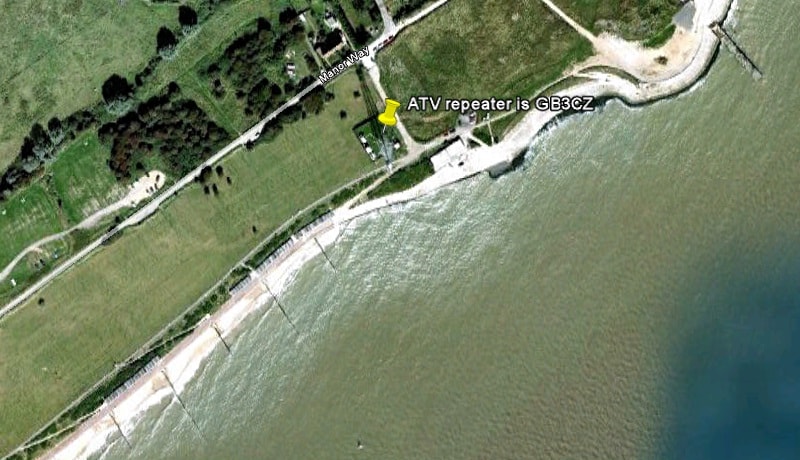
My local 13cms ATV repeater is GB3CZ and this is located on top of the Coastguard Tower, Holland Haven, Holland-on-Sea, Essex. Output is on 2432Mhz FM Horizontal 10W ERP 80 Meters Above Sea Level TM218172 JO 01 OT At the moment it is in TX mode only. It transmits a live image looking along the sea front towards Clacton on Sea. The Martello Tower Group have a receiver to put on site to make it a working repeater but with lack of interest from radio ham’s this is on hold! So PLEASE if you can receive GB3CZ send a signal report to the keeper and a show of interest of using it would be a big help.

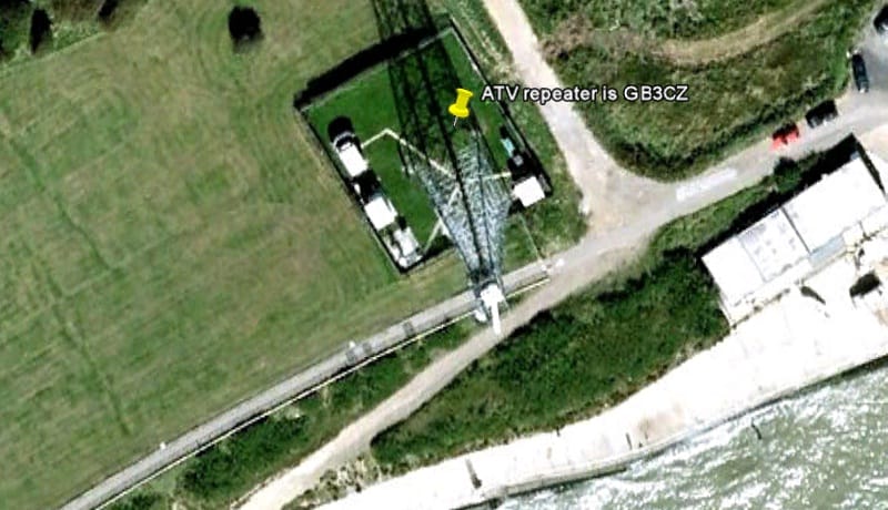
The alford slot for GB3CZ is at the top of this mast
Here are some photos from Google Earth
And one zoomed in a bit
What next?
Over the coming weeks I hope to build myself a 13cms offset dish to receive GB3CZ using a old Sky dish. I will take photos and measurements as I go about the build and will post the photos ETC here. The 6 modules shown below I will get wired up and tested and boxed. First I will get the 13cms ATV TX / RX built and tested, i’m not sure what I will be using the 23cms units for as I have not found anyone using 23cms ATV near me…
Today I met John G4BAO at the Ipswich radio rally and had a very interesting chat with him about 13cms amplifiers. He is working on a amplifier kit for 13cms around 30w so looking forward to that. John also sells a 23cms amplifier kit.
The 13cms RX module
The 13cms TX module
The Steve Dury TX/RX control module
The 23cms RX module
The 23cms TX module
The G1MGF TX/RX control module g1mfg TX/RX controler module
WiFi boosters for 13cms ?? 2.3~2.5GHz ??
Looking on places like Ebay there are many wifi boosters, the 1w and 2w output ones are around £40. I will do some more hunting before I buy one but would like to hear from anyone using one on 13cms. Here are some I have found with spec.
Specifications:
Frequency Range 2.4GHz
Output power 33dBm
Linear Pout 26dBm (@5.5%EVM) , 64QAM
Tx Mode Turn on Power > 2dBm
Tx Gain 13~17dBm
Rx Gain 8~12dBm
Turn on Power > 2dBm
Tx Gain 13~17dBm
Rx Gain 8~12dBm
Rx Noise Figure 3.0dB
VSWR, input/output < 2
DC supply 9~12V
Operating temperature -40~+70 oC
Product Description
Amplifies 802.11b/g wireless network/broadband signals
Supports standard SMA antenna connectors
Dramatically improved network coverage and range
33dBm (2W) output
Supports IEEE802.11/b/g
Amplification frequency range: 2400MHz ~ 2500MHz
Easy installation, plug and play
Package includes:
1 * Broadband amplifiers
Dimensions: 3.23 in x 1.93 in x 0.67 in (8.2 cm x 4.9 cm x 1.7 cm)
Model number AP08-1000
Operating Range: 2400 – 2480 MHz
Operating Mode: Bi-directional, TDD
Transmit Gain: 18 dB
Frequency Response: ±1 dB
Output Power: 1 Watt (+30 dBm)
TX Input Power: 5-16 dBm
Receiver Gain: 16 dB typical
Noise Figure: 3.5 dB typical
LED Inidicators: RED/ GREEN
Green/Red Blinking: Transmitting
Connectors: N-type, female, 50 Ohm
Lightning Protection: Quarter Wave Technology
Power Consumption: Tx = 1A, Rx = 130 mA 12V DC
Operating Temperature: -40°C to + 70°C
Dimensions: 152*71*25mm
30W Class A Linear RF amplifier 2.3-2.45 GHz 2304 ATV
You can find these on Ebay by searching
“30w Class A Linear”
30w 13cms Class A Linear
The text on the right is from the Ebay advert, The guy seems to have a good supply of them.
30w graph at 13cms ATV
Class A RF amplifier
Very linear Class A RF amplifier which I have removed from a new Spectrian high power Amp where it was used for driver for the main PA boards. This auction does include the 24v 80ma bias supply as suggested below at no cost to you. This amplifier has been selected, setup and tested for an output power of 30W from 2.3GHz to 2.35GHz with a linear gain of 35dB. Great amplifier for CW,AM, FM, ATV or SSB use from 2300MHz to 2350 @ 30W and to 2450MHz @ 25W. Input power for 30W output is typically 10mW or less! I have attached a plot of power vs frequency. The upper left reference tick marks the 100W (50dBm) point with 5dBm / vertical division. Frequency is 50MHz / division. Input drive for this example was 7.0dBm. Power requirement is 13-14V @ 10A and + 24 to +28v bias @ 50Ma. This bias is used for the gate voltage circuit on the power control FET. I do supply a miniature regulated DC-DC converter with this auction which takes 9-18v input with an output of 24v @ 125ma for generating this bias voltage. There is a logic level enable pin which requires grounding to enable power to this amplifier and can be used for a PTT/KEY control. The connector also has a direct temperature output pin with the function 10.0mV/degree F which measures the board temperature close to the 30W RF output GaAs FET (NEC S2527-30). Note that the output of this amplifier is protected by an internal 125W isolator! Here are the pin functions for the DC bias connector: Pins 1,2,3,4 are all +12 to 13Vdc @ 7.5 or so amps. Pins 5,6,7,8,10 are all ground. Pins 12,13 are N.C. Pin 11 is Logic level Low enable, normally floats high. This turns on the +12v to the internal transistors. Pin 14 is + 26V bias supply input @ 50Ma. Pin 9 indicates temperature = 10mV/degree F. This board comes mounted on a 1/4 inch thick aluminum heat spreader which has 6 mounting holes for mounting to a heat-sink. I am also suppling the 2 MCX .086 hard-line sections as well as the mating bias connector as shown. You will find it very easy to remove one of the MCX connectors from one end of these and replace it with a SMA .086 hard-line connector. Board dimensions are 6.5 x 4 inches.
13cms UK Repeater
23cms UK Repeater